02Thermal Shock Dynamics & Beam Coupling
Unlike metals or woods that melt or vaporize cleanly, glass exhibits extreme thermal shock sensitivity alongside low heat conductivity. When a pulsed 10.6 μm beam impinges upon soda-lime silicate glass, energy concentrates within a shallow absorption layer. The rapid expansion of this surface layer against the cold substrate beneath creates severe compressive stresses followed by high tensile rebound upon instant cooling.
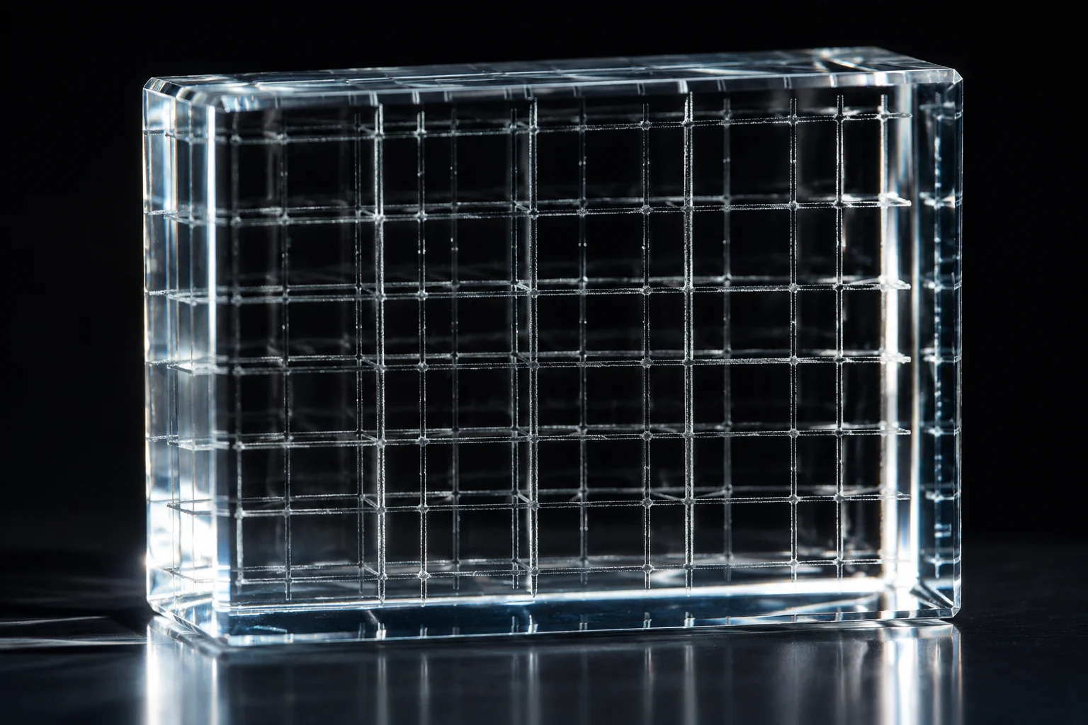
This thermal cycle produces deliberate microscopic fissures across the focal track. The resulting optical diffusion gives the mark its distinctive frosted white appearance. Maintaining energy density within the narrow window between clean micro-fracturing and structural failure demands strict regulation of scan speed and spot overlap.
“Engraving glass is fundamentally not about material removal; it is an exercise in controlling microscopic stress failures without letting crack networks breach the bulk volume.”
— Emily Davis, Senior Trial Analyst
03Observations Across Test Grids
Trial sequences run across annealed float glass sheets exposed substantial variations in shard formation, contrast sharpness, and edge integrity across fluctuating pulse frequencies and scan velocities:
- Sub-threshold exposure: Low power coupled with velocities exceeding 350 mm/s resulted in intermittent chipping, leaving faint marks with poor visibility against dark backdrops.
- Optimal fracture threshold: Moderate power at 220 mm/s produced dense, interconnected micro-chips with uniform light diffusion and negligible splinter dislodgement.
- Over-saturation zone: Excessive dwell time or multiple overlapping passes triggered radial fissure propagation, compromising substrate mechanical strength and causing delayed fracturing after cooling.
04Operational Protocol & Pre-Treatment Insights
Repeatable glass marking demands strict parameter discipline and deliberate surface preparation. Utilizing wet paper dampeners or specialized lithographic coatings stabilizes surface temperature during beam exposure, reducing airborne particulate release and ensuring uniform crack termination. Tempered glass substrates must be completely avoided under this processing protocol due to catastrophic internal stress relief risks.