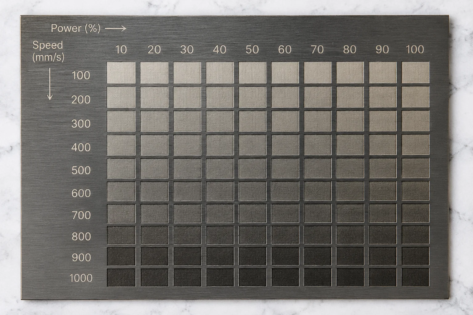
A. Material Test Purpose
The LightBurn Material Test exists to answer one narrow question: how does a specific piece of stock respond to a controlled range of energy inputs on a specific machine, on a specific day. It is a comparison instrument, not a promise. The grid it produces gives an operator a visual map of where marking begins, where it stabilizes, and where it breaks down into charring or erosion.
Used well, the tool removes guesswork from the first setup of an unfamiliar substrate. Used carelessly, it produces a false sense of certainty — a single attractive cell detached from the conditions that created it.
B. Test Grid Variables
A material test grid varies two parameters systematically while holding the rest constant. Most commonly the axes map speed against power, but any pair of machine inputs can be assigned. Before reading any cell, the operator should confirm which variable sits on which axis, the direction in which each axis increments, and the count of steps the generator produced.
Secondary variables still shape the outcome even when they are not on an axis: line interval, number of passes, focus offset, air assist, and layer mode. Every one of them belongs in the trial record alongside the grid itself.
C. Speed and Power as Controlled Inputs
Speed and power act as a coupled pair. Higher travel speed shortens beam dwell per unit length; higher power raises instantaneous energy delivery. A cell only becomes meaningful when both inputs are read together — a dark mark at high speed tells a different story than the same darkness achieved slowly.
Ranges should be chosen conservatively: wide enough to bracket the expected working window, narrow enough that adjacent cells differ visibly. This guide intentionally publishes no preset ranges; valid bounds depend entirely on the laser source, optics, and substrate in front of the operator.
D. Passes and Other Relevant Settings
Multiple low-energy passes behave differently from one high-energy pass even when total delivered energy is similar. Each successive pass meets a surface already altered by heat — carbonized, discolored, or textured — so cumulative exposure must be logged, not assumed.
Line interval, cross-hatch angle, kerf offset, focus height, and assist gas pressure all deserve explicit entries in the trial sheet. A grid burned with an undocumented assist setting cannot be faithfully repeated later.
E. Recording Hardware and Material Context
A test grid without context is a picture, not a record. The ledger entry should name the laser source type and wattage, the lens focal length, the machine model, and the LightBurn version used to generate the pattern.
Material context matters equally: substrate species or alloy, nominal thickness, surface finish, vendor batch, and ambient conditions such as temperature and relative humidity. These fields explain why two identical files can engrave differently on two mornings.
F. Interpreting the Visual Grid
Reading a grid means looking for transitions, not favorites. The informative boundaries are the threshold where a mark first becomes permanent, the plateau where contrast stays even across several adjacent cells, and the onset where excessive energy produces char, melt, or cracking.
Inspection improves with method: wipe residue away before judging contrast, tilt the specimen under raking light to expose relief, and compare edge sharpness rather than darkness alone. A robust working cell sits inside a stable cluster, not on the edge of a failure zone.
G. Why a Successful Test Does Not Guarantee Repeatability
A test grid captures a moment. Tube output drifts with age and temperature, lenses accumulate film, humidity swells organic stock, and sheet thickness varies between deliveries. A cell that looked ideal last week can land in a different regime today.
The defense is documentation rather than memory. Re-running a small confirmation grid before production, and comparing it against the archived sheet, reveals drift long before a full workpiece is committed.
H. Illustrative Test Sheet
The sheet below is an empty documentation template — an example of the fields an operator might fill while reviewing a grid. It is illustrative only and intentionally contains no parameter values.
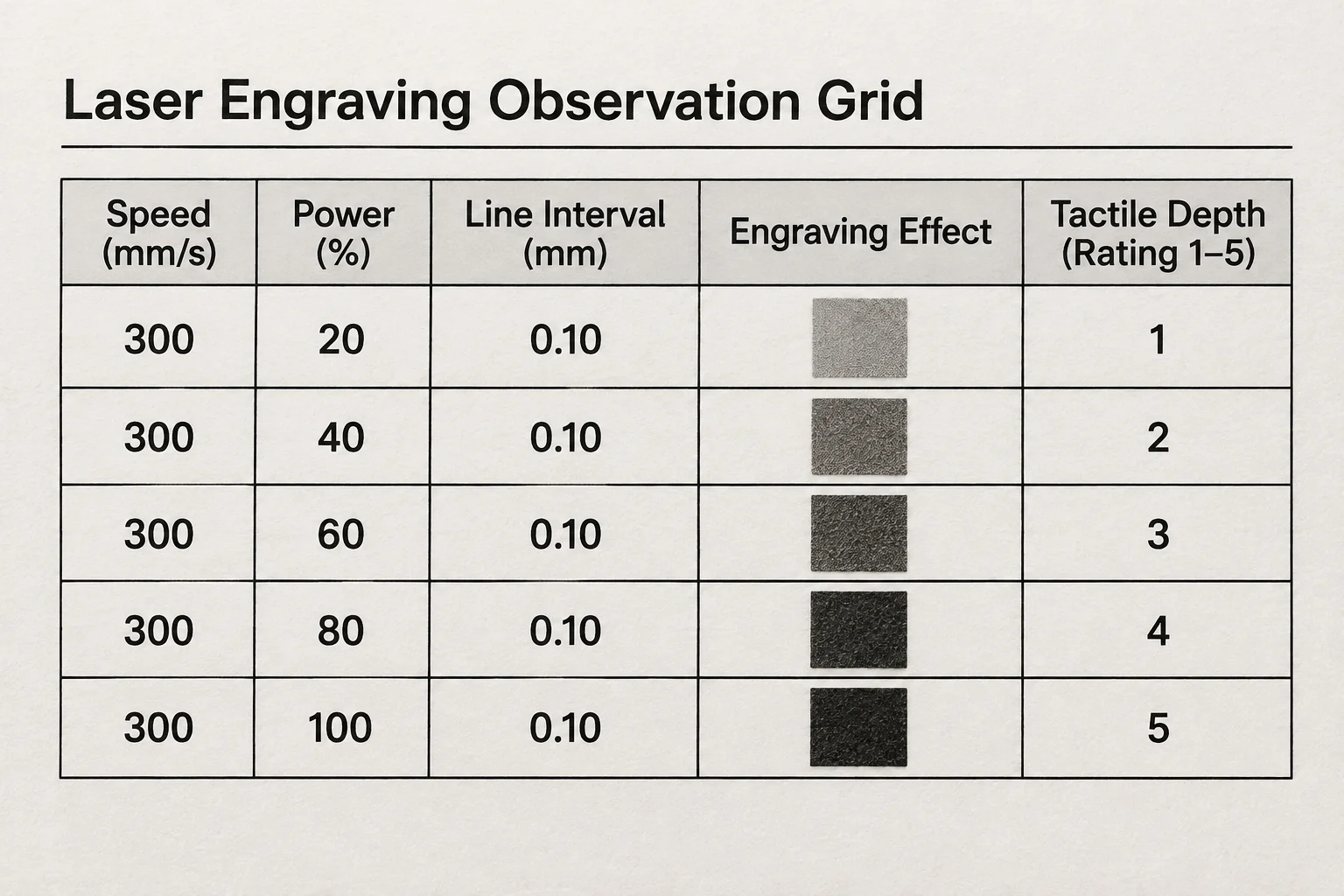
- Specimen field: material, batch, thickness, and surface preparation notes.
- Axis fields: which input is on each axis and the step direction of each increment.
- Observation fields: threshold cell, stable cluster extent, and first failure symptoms.
- Context fields: machine, optics, assist pressure, ambient humidity, and operator initials.
I. Brand-Specific Featured Scenario: Comparing Three Test-Grid Regions
The annotated drawing below shows how a LightBurn training grid can be divided into three review regions — A, B, and C — for structured note-taking. It is a schematic created for this guide: it does not depict results from a real test, and no speed or power presets are suggested by it.
How an Operator Might Record Observations
While reviewing each region, an operator could fill an observation line per region rather than per cell:
- Region A: where the first durable mark appears, and whether edges stay clean at the threshold.
- Region B: how wide the visually stable cluster is, and whether neighboring cells match under raking light.
- Region C: at which step charring, melt, or micro-cracking first becomes visible.
These region notes convert a wall of cells into three short sentences an engineer can act on later — a pattern for observation, not a result.
J. Product Boundary
LightBurn is the third-party laser design and control application referenced in this guide. MaterialTrial Ledger is an independent educational resource: it is not affiliated with, endorsed by, or sponsored by LightBurn or its developers. All references to the software describe documentation methodology only, and nothing here constitutes official guidance, support material, or verified machine settings.