02Interlayer Thermal Degradation in Layered Stock
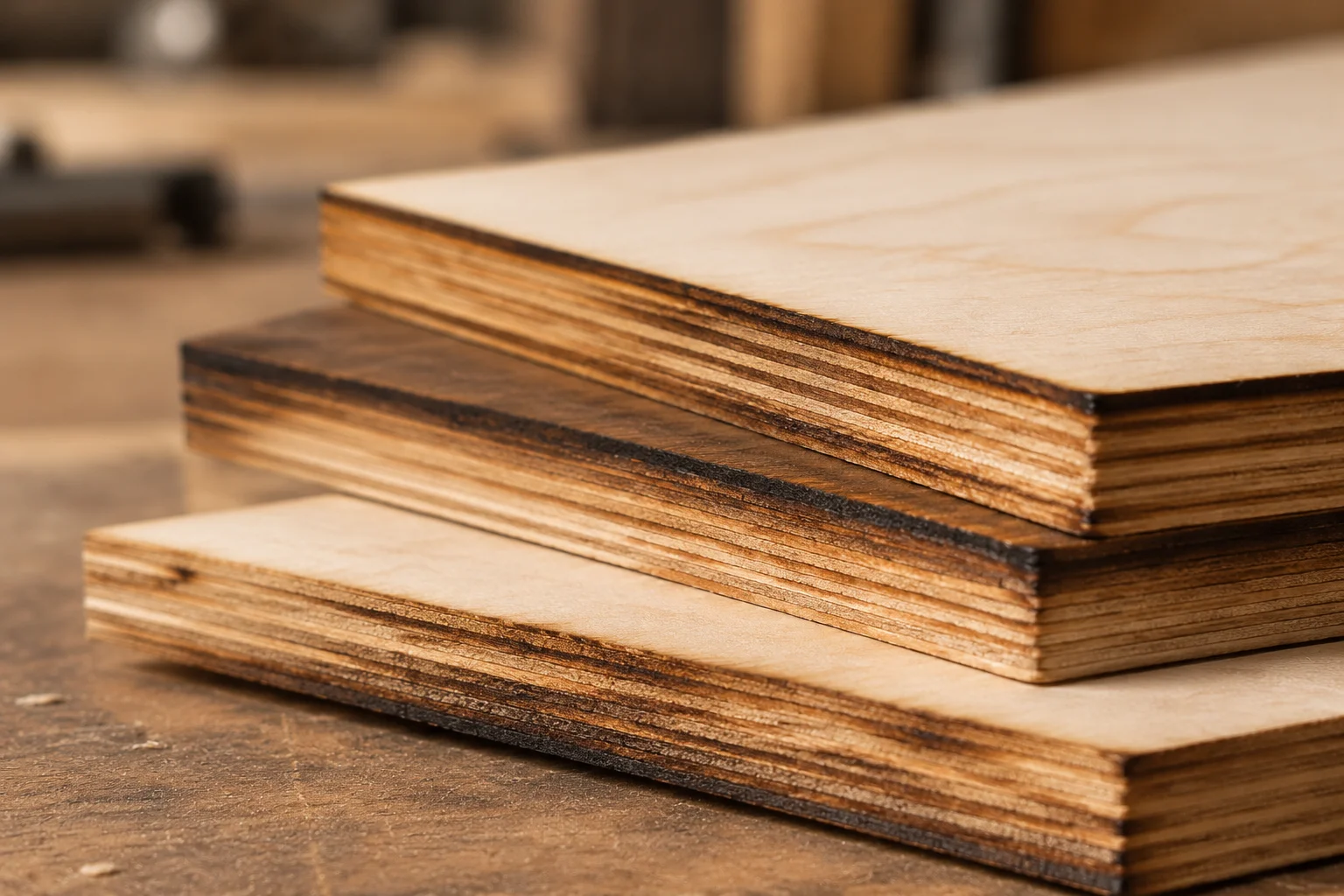
Plywood edge charring manifests differently than discoloration on solid hardwood stock. During beam penetration through multi-layer Baltic birch, the laser encounters alternating bands of low-density wood fiber and high-density synthetic binder. The organic fibers vaporize rapidly at moderate temperatures, whereas synthetic phenolic or urea adhesives demand sustained thermal exposure to break down. This uneven thermal demand causes operators to lower travel speed, inadvertently baking the surrounding timber layers.
As heat conducts laterally through the dense glue seams, volatile resins convert into sticky carbonaceous residues that coat the cut profile. When operators wipe the piece after cutting, this oily char stains adjacent face veneers. Resolving the problem requires treating the plywood cut not as a wood-burning task, but as an alternating fiber-and-polymer evacuation challenge.
“Excessive charring on composite plywood edges is almost always a diagnostic symptom of inadequate vapor ejection velocity, rather than simply applying too much beam wattage.”
— Robert Chen, Laser Diagnostics Specialist
03Empirical Measurements Across Variable Assist Pressures
The trial monitored cross-sectional edge discoloration across thirty identical 6 mm birch specimens using a focused 10.6 µm optical path. Each run preserved identical beam wattage while step-adjusting line velocity and coaxial air delivery from an oil-free pneumatic compressor:
- Low pressure (0.6–0.9 bar): Heavy soot deposition extended up to 1.8 mm onto bottom veneer faces, leaving friable charcoal margins that transferred powder to touch.
- Intermediate pressure (1.2–1.6 bar): Surface flash burns disappeared, yet microscopic inspection revealed localized pocket blistering around inner resin voids.
- Elevated pressure (2.2–2.6 bar): Produced dry golden-amber flanks with zero transfer soot, eliminating secondary cleaning processes prior to assembly or bonding.
04Reproducible Parameters for Clean Kerf Separation
Achieving minimal charring without compromising dimensional stability demands balanced gas velocity and focal geometry. Shifting the focal waist slightly inward (one-third into sheet depth) prevents premature beam divergeance at the exit layer. Paired with high-pressure laminar air through a narrow 1.5 mm cone nozzle, this configuration shears vaporized binder from the cut trench before thermal combustion can spread into the neighboring wood fibers.