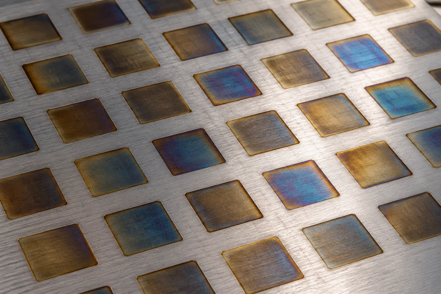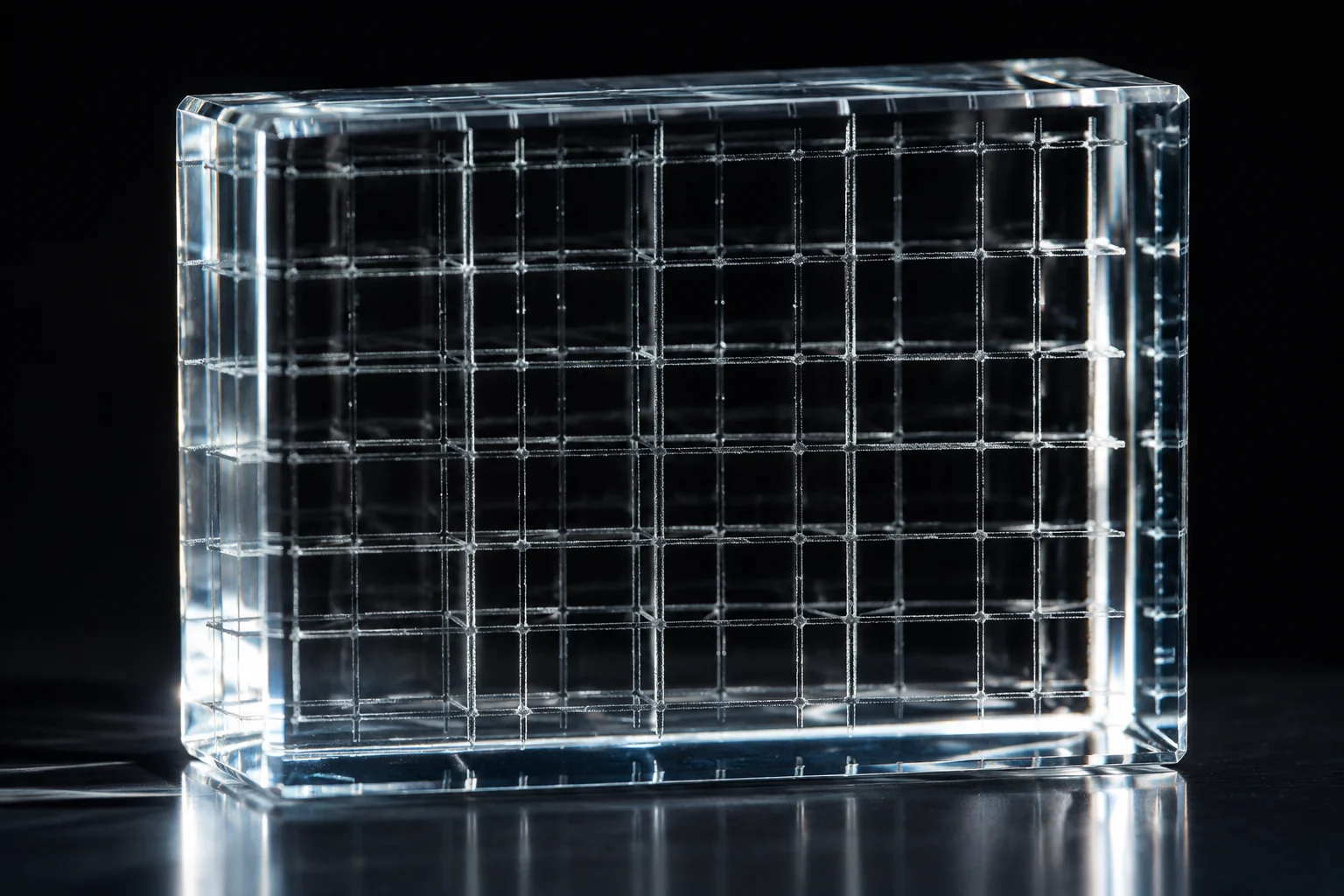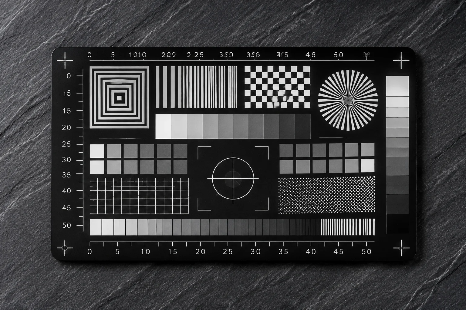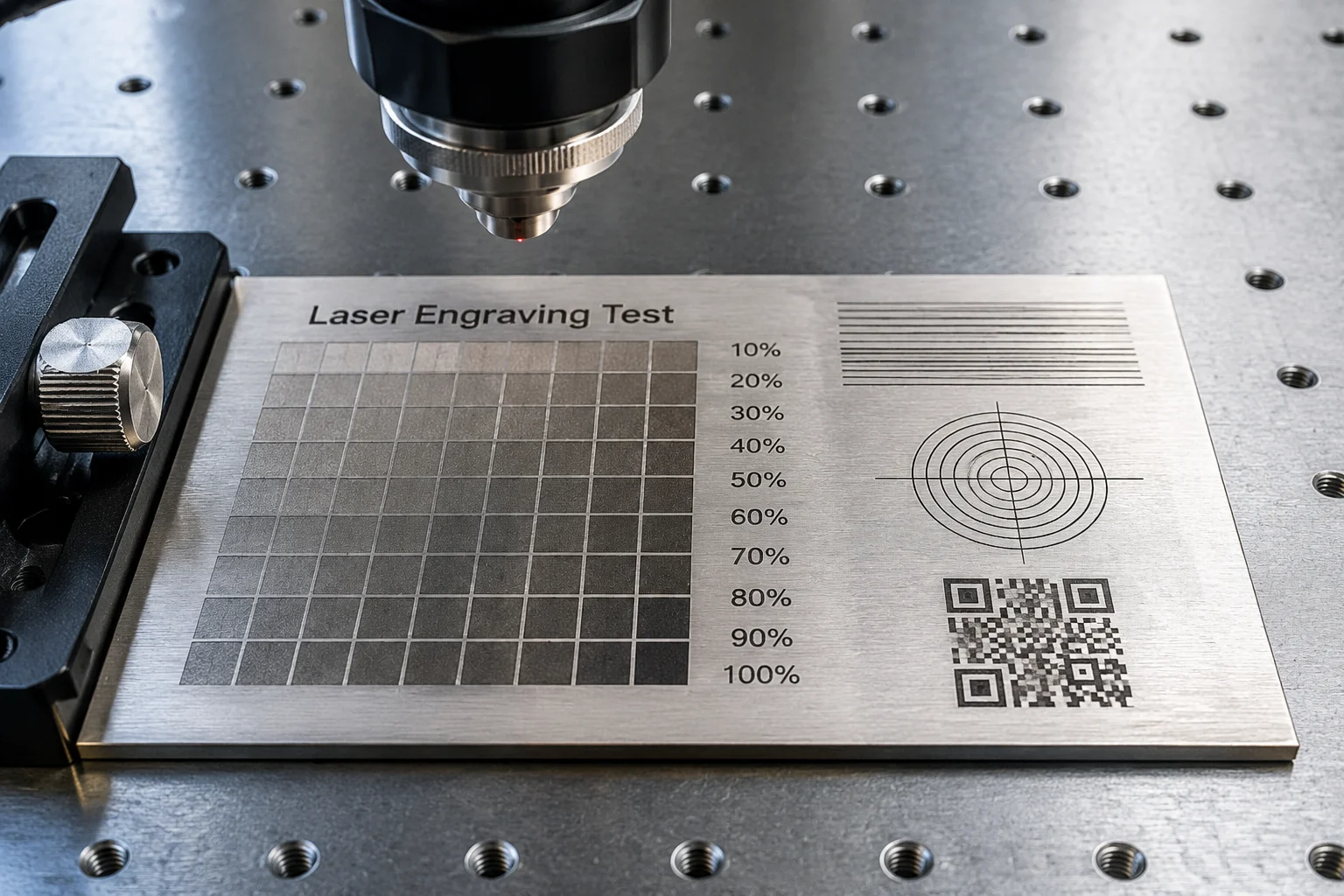
Calibrated laser test grid on industrial substrate
Laser Trial Documentation

Make Material Tests Easier To Compare

Explore how material conditions, test patterns, and recorded observations influence the interpretation of laser engraving trials.
MaterialTrial Ledger publishes independent educational cases and practical documentation methods.

Methodology Shift

Eliminate Guesswork in Laser Material Testing

Unrecorded laser parameters turn identical substrate batches into scrap. Systematic trial ledgers preserve verified laser power, interval, and speed data for dependable production.

Current Trial Friction

Ad-Hoc Testing
  • Inconsistent Beam Outcomes

    Re-running previous test settings on new stock yields varying contrast, excessive charring, or incomplete penetration due to unrecorded baseline deviations.

  • Lost Layer Configurations

    Optimal focal offsets, air assist bar pressure, and line intervals are scattered across temporary scrap pieces or forgotten between production runs.

  • Wasted Calibrated Stock

    Each project restart consumes expensive prototype material while operators manually recreate matrix sweeps that were solved weeks prior.

Ledger Documentation

Standard Protocol
  • Reproducible Grid Records

    Every parameter matrix couples laser power, feed rates, and optics height directly to substrate vendor batch IDs for repeatable engraving contrast.

  • Standardized Observation Sheets

    Centralized trial indexes capture kerf compensation, micro-fracture behavior, surface sheen, and thermal edge condition in uniform logs.

  • Predictable Production Hand-Off

    Technicians execute production files with confidence, reducing trial iterations to a single verified reference swatch per material lot.

Terminology Reference

Foundational Parameters Explained

Single-line operational definitions eliminating ambiguity across laser engraving trials, beam calibrations, and documentation records.

SRF-01Surface

Contrast

The visual tonal variance produced between untouched stock and laser-altered surface fibers or oxides.

OPT-01Optics

Focal Length

The measured distance from optical lens center to the beam waist where energy density peaks.

OPT-02Optics

Kerf

The dimensional width of substrate material completely sublimated, vaporized, or evacuated by the cut.

MOT-01Motion

DPI

The linear frequency of concentrated pulse points addressed per inch along the motion vector axis.

OPT-03Optics

Spot Size

The narrowest waist diameter of converged coherent radiation dictating minimum line resolution.

MOT-02Motion

Line Interval

The physical step distance indexed between successive raster scanning passes across the work surface.

SRF-02Surface

Air Assist

Pressurized gas directed directly into the focal trench to displace molten ejecta and suppress flaring.

MOT-03Motion

Pulse Rate

The emission discharge frequency dictating thermal overlap and mechanical pulse spacing during transit.

Protocol Architecture

Stages & Observation Checkpoints

Every verified ledger entry follows a non-destructive audit sequence. Standardizing data capture before, during, and after laser exposure isolates physical variance from beam optics.

01Phase Initial

Pre-Exposure Baseline

Substrate characterization prior to thermal exposure. Eliminates batch variability from downstream optical readings.

Audit Checkpoints
  • Substrate caliber & core density
  • Surface moisture & coating film
  • Focal plane true datum zero
02Execution

Test Grid Processing

Systematic stepped parameter matrices recorded across identical coordinate fields under steady assist conditions.

Audit Checkpoints
  • Velocity vs. power delta ratios
  • Line interval & pulse frequency
  • Assist gas nozzle volumetric flow
03Micro-Analysis

Thermal Metrology

Optical measurement of heat-affected bands, depth profiles, and edge carbonization under high-contrast illumination.

Audit Checkpoints
  • Kerf oxidation & boundary char
  • Trench depth micrometer scan
  • Micro-fracture propagation zone
04Archival

Ledger Indexing

Consolidation of spectral readings and process parameters into reproducible, hardware-agnostic benchmark indexes.

Audit Checkpoints
  • Spectrophotometric gray index
  • Second-pass variance margin
  • Digital sheet archival format
Empirical Test Methodology

Calibrated Grid Comparison: Zones A, B & C

Universal machine presets do not exist. Reliable laser records demand documenting ambient humidity, focal deviation, assist gas pressure, and thermal dwell alongside speed and power variables.

Diagram 04-A Reference Axis: Power [W] vs Feed Rate [mm/s]
Active Matrix: 100mm × 100mm
ZONE A ZONE B ZONE C Sub-Threshold Equilibrium Thermal Saturation 10% 25% 50% 75% 90% 400 mm/s 250 mm/s 80 mm/s
Select Sector to Inspect

Zone A: Sub-Threshold Ablation

Low Density

Energy input falls below the material vaporisation enthalpy. High transit velocities (350–450 mm/s) coupled with short dwell times produce incomplete phase change, surface dusting, or uneven micro-grooving.

Logged Power Range: 10% – 30% (nominal 40W tube)
Assist Pressure: 0.8 Bar Dry Air (Laminar)
Focal Spot Shift: ±0.00 mm (True Waist)
Typical Artifact: Intermittent line skipping, surface halo

Zone B: Nominal Equilibrium

Repeatable Zone

Thermal equilibrium zone where energy deposition precisely equals the heat capacity and reaction threshold of the stock. Minimal Heat Affected Zone (HAZ), smooth edge definition, and stable repeatability.

Logged Power Range: 35% – 60% (nominal 40W tube)
Assist Pressure: 1.5 Bar Dry Air (Coaxial)
Focal Spot Shift: ±0.05 mm Tolerable
Typical Artifact: Sharp transitions, zero kerf bulge

Zone C: Thermal Over-Saturation

Excess Energy

Excessive energy density causes prolonged thermal soaking. Low travel speeds (under 120 mm/s) lead to melted trench edges, internal micro-fissuring, extensive re-deposition of condensation plumes, and substrate distortion.

Logged Power Range: 65% – 95% (nominal 40W tube)
Assist Pressure: 2.0 Bar (Turbulent expulsion)
Focal Spot Shift: Severe beam waist over-etch
Typical Artifact: Venting residue, internal stress fractures
01

Ambient State Logging

Relative humidity and shop temperature directly skew heat dispersion. Logging hygrometer readings isolates climate drift from optical wear.

02

Gas Assist Geometry

Nozzle standoff and laminar flow dictate whether vaporized particulate clears cleanly or condenses back across unlasered adjacent cells.

03

Focal Waist Integrity

A 0.25mm focal offset completely transforms power density. Test matrices must establish physical gauge verification before firing first pulse.

Software Execution Guide

Translating Documentation to LightBurn Material Test Arrays

Learn how to populate test matrices in LightBurn while embedding systematic ledger fields into your recurring test protocol.

Empirical Documentation

Documented Trial Cases

Rigorous records evaluating laser interaction, thermal reaction boundaries, and repeatability profiles across industrial substrates.

Empirical Documentation Index

Educational Trial Records & Methodology

Systematic evaluations analyzing beam delivery variations, substrate behavioral traits, and standardized diagnostic protocols for laser testing verification.

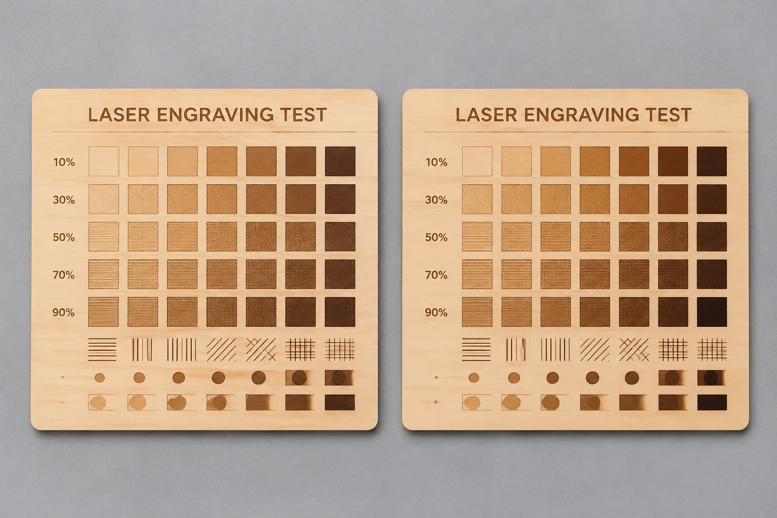
Two material test grids side by side for comparison

What Makes Two Material Tests Comparable

Key calibration standards, focal depth verification, and power-to-speed ratios required to ensure distinct laser test matrices yield valid, repeatable comparative data across trials.

Magnifying glass over raw wood grain showing pores

The Missing Material Condition

An exploration into substrate moisture contents, surface oxidation rates, and ambient workshop deviations that dramatically alter beam interaction outcomes before execution.

Laser test grid on anodized aluminum specimen

How to Read a Test Grid

Systematic analysis of kerf dimensional variance, trench bottom consistency, thermal edge degradation, and microscopic contrast transitions across power levels.