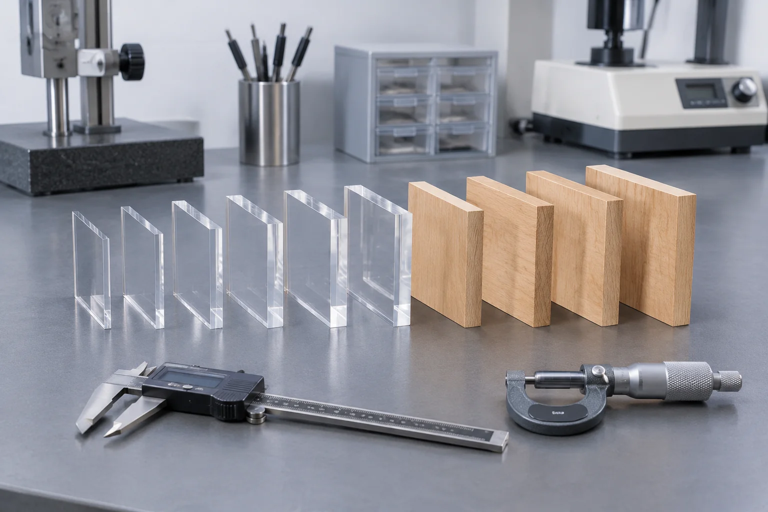
Beam Geometry and the Rayleigh Range
A common misconception in experimental laser cutting assumes a focused beam moves through material as a cylindrical column of uniform diameter. A focused optical laser beam actually converges into an hourglass waist before rapidly diverging outwards. The functional vertical corridor where spot diameter remains sufficiently concentrated to cut cleanly is defined as the Rayleigh range. When sheet thickness stays within this narrow band, the cut edge appears nearly perpendicular. As sheet gauge expands beyond the beam waist height, divergence begins reshaping the cut channel.
Thin sheet stocks measuring under 2 mm rarely challenge the focal depth of a standard 2.0-inch lens. Once material thickness reaches 6 mm, 8 mm, or 10 mm, the beam spot at the bottom surface operates far beyond its tightest diameter. The result is a natural V-shaped taper, excessive bottom kerf width, and uneven edge heating. Documenting thickness is therefore not merely a record of raw material size; it establishes whether the optical system can physically deliver uniform irradiance across the entire cut depth.
Focal Offset Mapping Across Thickness Steps
Calibrating cuts across progressive gauges requires shifting the focus reference point away from the top surface. Setting zero focus at the top plane concentrates maximum energy density on the surface layer, while the lower sections receive a wide, unfocused spot with sluggish cut penetration. Subdividing thickness steps and shifting the focal point downward balances the beam waist inside the core of the sheet.
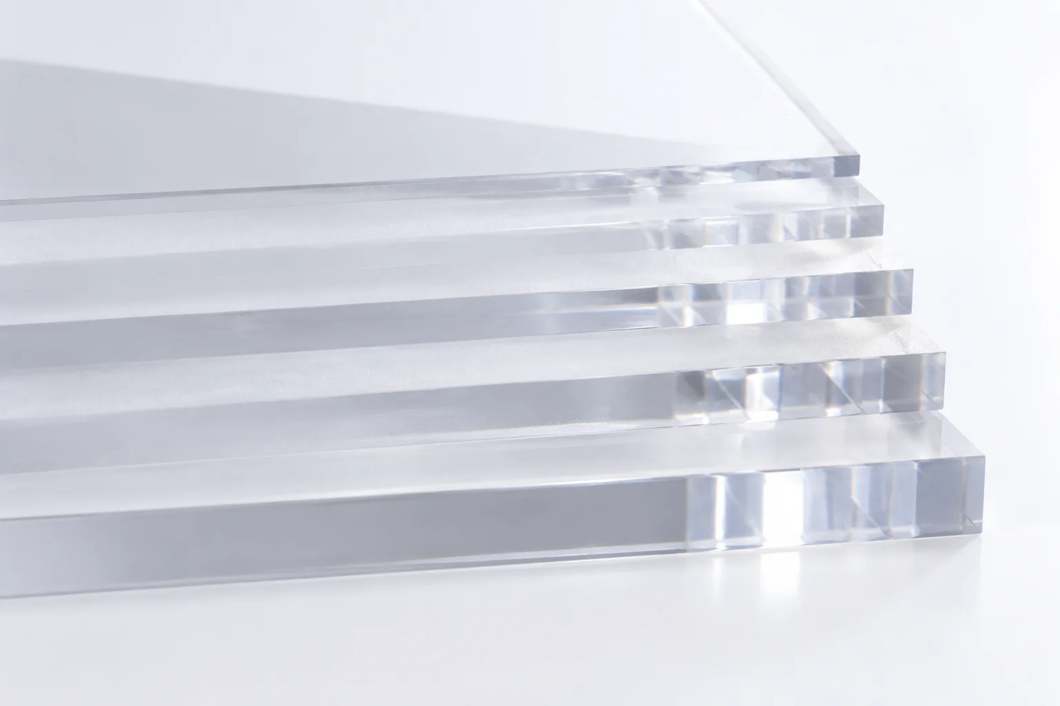
In trials conducted across acrylic stocks ranging from 2 mm to 10 mm, shifting focus to 35 percent depth on 5 mm sheets and 45 percent depth on 8 mm sheets visibly reduced edge draft angles. The bottom kerf closed inward to mirror the top opening, creating a symmetrical hourglass profile instead of an exaggerated downward flare. Calibrating thickness requires pairing exact caliper measurements with verified Z-axis focal offsets.
Heat Accumulation and Kerf Profile Variations
Varying material thickness introduces distinct thermal dynamics that overturn simple linear calculations. Increasing sheet thickness from 3 mm to 6 mm doubles the physical volume of material needing sublimation or combustion along the cut line. The additional mass draws away thermal energy through lateral conduction, requiring significantly higher overall energy exposure than simple two-to-one arithmetic would predict.
Empirical Observations on Kerf and Surface Integrity
During multi-gauge test runs on cast acrylic and hardwood cores, specific shifts in kerf morphology and edge finish were documented as thickness increased under constant focal parameters:
- Gauges below 3 mm maintain near-vertical edges with under 0.05 mm kerf variance between top and bottom surfaces.
- Sheets between 4 mm and 6 mm exhibit measurable beveling unless the focal point is submerged between 1.2 mm and 1.8 mm below the top surface.
- Gauges exceeding 8 mm show extensive heat-affected zones and slower vapor clearance, requiring elevated assist air pressure to prevent secondary combustion in the cut trench.
Protocols for Calibrating Thickness Variations
Material sheets sold under standard nominal labels frequently exhibit manufacturing variations. A sheet cataloged as 6.0 mm cast acrylic often measures between 5.4 mm and 6.6 mm across opposite edges of the same production panel. When operators apply saved speed and power presets without verifying real thickness using precision micrometers, focus errors propagate directly into the cut geometry.
A robust trial ledger demands that every test matrix records the verified mechanical caliper reading alongside focal offset settings. Treating thickness as a dynamic physical variable rather than a fixed label ensures cutting repeatability, preserves square assembly joints, and eliminates inexplicable edge variations between batches.